
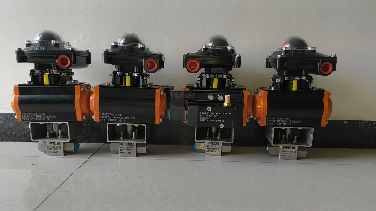
Pneumatic Directional Control Valve - Supreme Valves India
4.8/5 (82 reviews) ISO 5211 India Made
Pneumatic Components

Pneumatic Directional Control Valve | 3/2 Way Valve

Pneumatic directional control valves (3/2, 5/2, 5/3 way). Solenoid or pilot operated. G1/8 to G1/2 ports. For pneumatic system logic control and actuator direction switching.

Key Specifications

Category: Pneumatic Components
Brand: Supreme Valves India
Origin: Ahmedabad, Gujarat
Certification: ISO 9001:2015

In-stock: Standard sizes ship within 3-5 working days from Ahmedabad. Export packaging available.

Request Enquiry WhatsApp Download Datasheet

Materials of Construction (MOC)

Component Material Specification
Body & Bonnet Ductile Iron (ASTM A536 / EN-GJS-400-15)
Stem / Spindle SS 410 / SS 420
Seat / Trim EPDM / NBR / Bronze

Technical Specifications

Parameter Specification / Standard
Manufacturing / Design Standard EN 1171 / AWWA C509 / BS 5163
Testing Standard API 598 / EN 12266-1
Pressure Rating PN16 / PN25

Material of Construction

S.N.Parts NameMaterial
01BODYASTM A 216 Gr. WCB
02BONNETASTM A 216 Gr. WCB
03BONNET FLANGEASTM A 216 Gr. WCB
04STEMAISI 304 / AISI 410 ( 13% CR. )
05PLUGAISI 304 / AISI 410 ( 13% CR. )
06SEAT RINGAISI 304 / AISI 410 ( 13% CR. )
07GLAND BUSHAISI 304 / AISI 410 ( 13% CR. )
08GLAND PLATEM.S.
09BONNET STUD & NUTASTM A 193 Gr. B7 / ASTM A 194 Gr. 2H
10ACTUATORALUMINIUM
11GLAND PACKINGMETALLIC WIRE REINFORCED GRAPHITED ASBESTOS

Dimension Tables

ClassSizeInchM.M.ABØCØDHH1ØMNPCD
1501"1"2518411.23589.013052015.9460.4
1501.1/2"1.1/2"4018414.24398.513752015.9470.0
1502"2"5018415.751108.014359519.1479.0
1502.1/2"2.1/2"6522217.273127.020059519.1498.5
1503"3"8025419.092152.022067519.14120.5
1504"4"10027623.9105178.025069519.14140.0
1505"5"12529824.0127190.526570022.24152.4
1506"6"15035225.4157229.029070022.28190.5
3001"1"25190.514.03595.013852819.1466.5
3001.1/2"1.1/2"40193.616.043117.314852822.2482.5
3002"2"50197.017.551124.015560619.1489.0
3002.1/2"2.1/2"65235.020.573155.521562222.24114.0
3003"3"80267.022.092165.022868022.28127.0
3004"4"100292.025.0105190.525870022.28148.0
3005"5"125318.028.5127209.528371022.28168.0
3006"6"150368.032.0157254.030871022.28200.0

Frequently Asked Questions

What do the numbers in 3/2, 5/2, 5/3 valve designations mean?

The numbers refer to ports and positions: the first number is the number of ports, the second is the number of valve positions (switching states). A 3/2 valve has 3 ports (inlet, outlet, exhaust) and 2 positions (open/closed). A 5/2 valve has 5 ports (P=supply, A/B=outputs, R/S=exhausts) and 2 positions (A=P or B=P). A 5/3 valve has 5 ports and 3 positions (A=P, B=P, and a closed center position). The 3/2 is used for single-acting cylinders, 5/2 for double-acting cylinders, and 5/3 for circuits requiring a neutral center position.

What is the difference between solenoid and pilot operated directional valves?

Solenoid valves use an electromagnetic coil to directly shift the valve spool - providing fast response (15-30ms) but limited to small flow sizes (typically up to Cv 0.8). Pilot operated valves use compressed air to shift a larger spool - they require minimum pilot pressure (usually 2-3 bar) but can handle much higher flow rates (Cv 1.0 and above). For most industrial pneumatic circuits, pilot operated valves are preferred for sizes above G1/4 because they require lower electrical power, generate less heat, and can handle larger flows without increasing coil size.

What is a 5/3 directional control valve with closed center?

A 5/3 valve with closed center (also called blocked center) has all five ports (P, A, B, R, S) blocked in the center position - the cylinder is locked in position and cannot drift. This is essential for safety-critical clamping or holding applications where cylinder position must be maintained when the valve is in neutral. Other center configurations include: P=centered (both ports connected to supply - pressure locked), A/B=centered (both exhausted - free movement), and A/B/P=centered (all blocked). Select center configuration based on your safety and positioning requirements.

How do I troubleshoot a pneumatic directional valve that won't shift?

Troubleshooting steps for stuck directional valves: 1) Verify air supply pressure is above minimum pilot pressure (2-3 bar for pilot operated); 2) Check for debris in the supply air - install a filter upstream; 3) Test the solenoid coil resistance (should be within 10% of rated value); 4) Verify voltage is reaching the coil at the terminal; 5) For pilot valves, check pilot exhaust port is not blocked; 6) Inspect spool for corrosion or dry media damage (in contaminated environments). If the coil is fine and supply is good, the valve body likely needs replacement.

What is the lifespan of a pneumatic directional control valve?

Quality directional control valves typically provide 10-20 million switching cycles before wear affects performance. Spool clearance and seal condition are the primary wear factors. Key factors affecting lifespan: air quality ( moisture and particles accelerate wear); cycling frequency (high-frequency cycling reduces life); pressure (operating above rated pressure accelerates seal wear); and temperature (extreme temperatures degrade seals). Use FRL units (Filter-Regulator-Lubricator) to maximize valve life. Regular preventive maintenance (annual coil replacement, seal kit) extends service life significantly.